
Introduction
The rapid prototyping capabilities at 3DPhacktory (see our industrial design page) are well suited for modeling injection molded products. Since most of our client work is private, I thought I’d show how you can model an existing injection molded part that I found at the nearby mall for $4 – an 8 GB USB key!
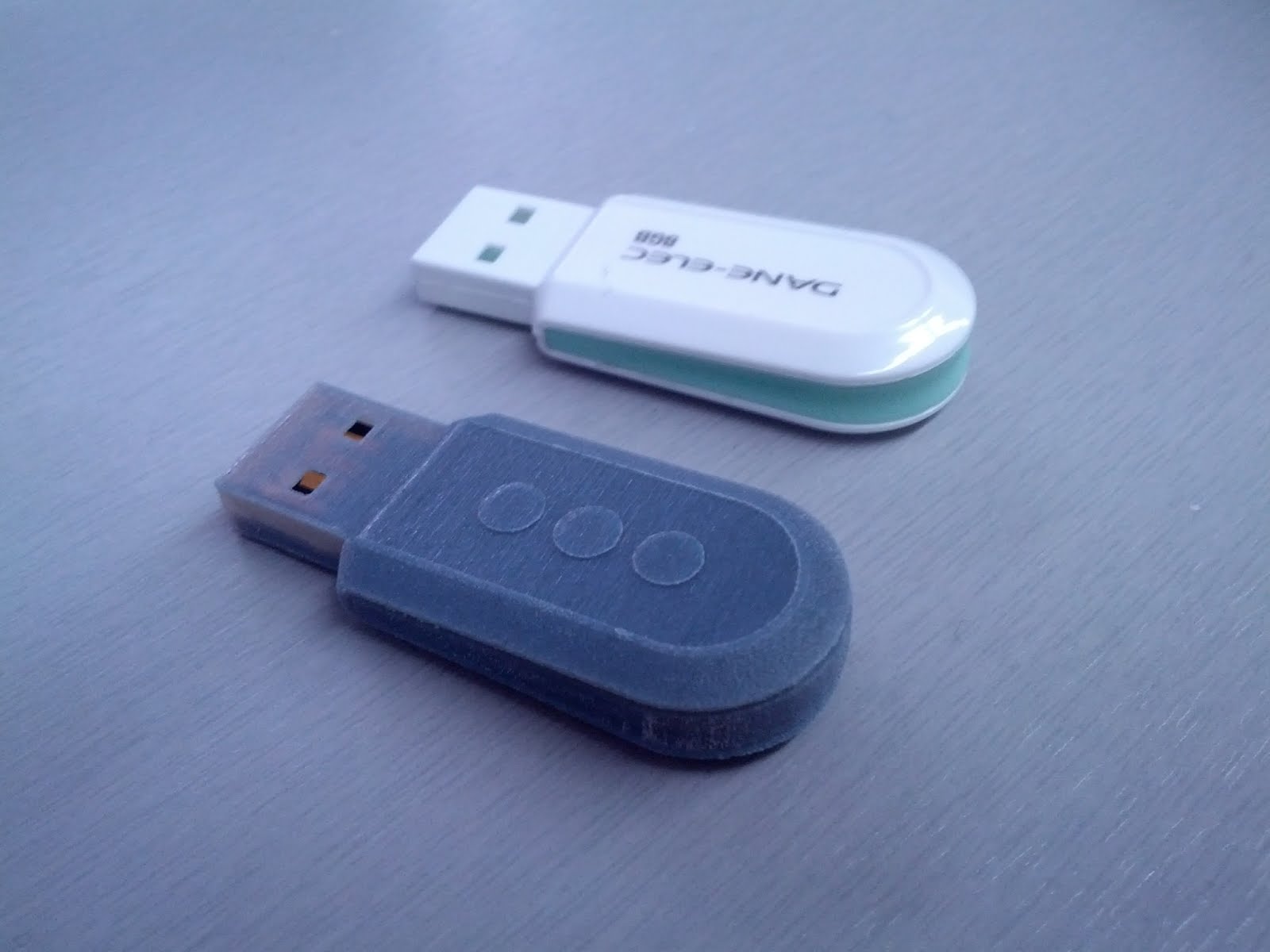
The injection molded part, with the completed rapid prototype in the foreground.
Important Features
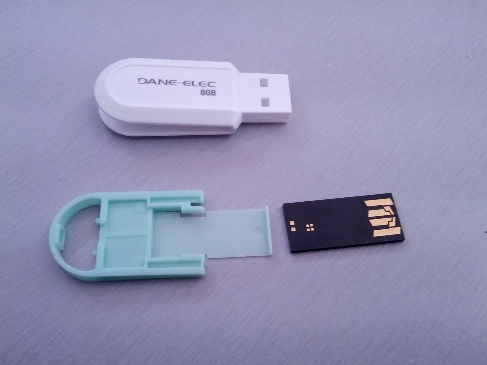
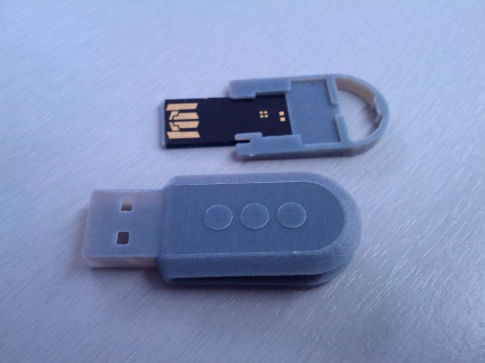
The casing, carriage and memory module that compose the USB key.
The key comes in three parts. An outer casing, a carrier, and a memory module. There are some interesting design choices:
- The memory module is kept inside the carrier in part by a thin shelf at the key’s leading face.
- The carrier and casing are keyed to each other by a protrusion on the left side of the casing.
- Two snap fits keep the casing closed on the carrier, while one snap keeps the carrier from pulling backwards.
- Sections of material are removed from the carrier so it slides smoothly into the casing without catching on the snap fits.
CAD Model
If we were designing this product, we’d be working from a CAD model at this point. Since we’re going in reverse, I’ve generated one from the injection molded part. You can download the design files (including SolidWorks 2012 and STL files).
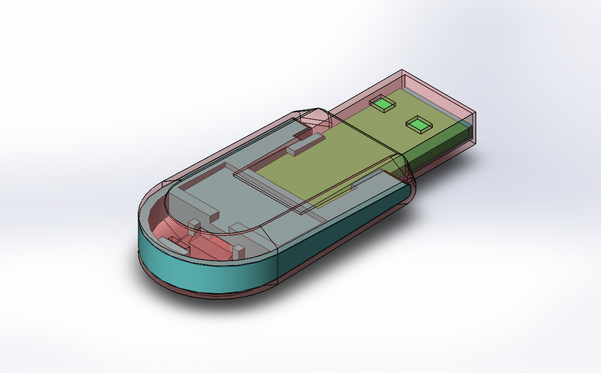
A CAD model of the USB key, showing the casing in transparent red, the carrier in cyan and the memory module in green.
Deciding When To Print
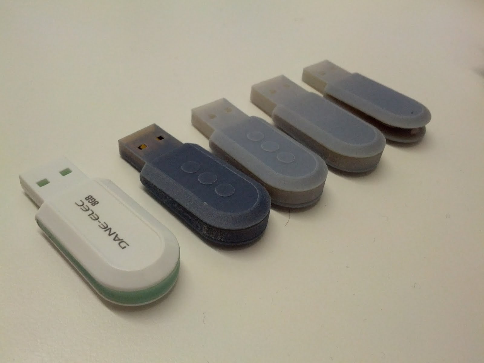
Four prints made during this design shown with the original part.
You’ll generally want to print once you’ve done as much work as you can in CAD. This will either be before you create expensive tooling, or before you need an appearance model for a presentation or trade show.
After this, you can then decide if subsequent changes have added enough uncertainty to warrant another print.
On the other hand, consider printing a model early on before your CAD model is complete. My first print was based off an incomplete CAD model, but it clearly communicated what I was working on, sparked new ideas and gave a sense of momentum.
I ended up with 4 prints in total. From right to left, they are:
- R1: Overall shape, fit with existing parts, communication tool.
- R2: Increase thickness, change side profile to match intended look.
- R3: Fix USB plug size, added 3 raised circles.
- R4: Choose a more flexible material for better modeling of snap fits.
For the rest of the article, we’ll discuss evaluating R4, the final print.
Evaluating The Print
Hand Fit
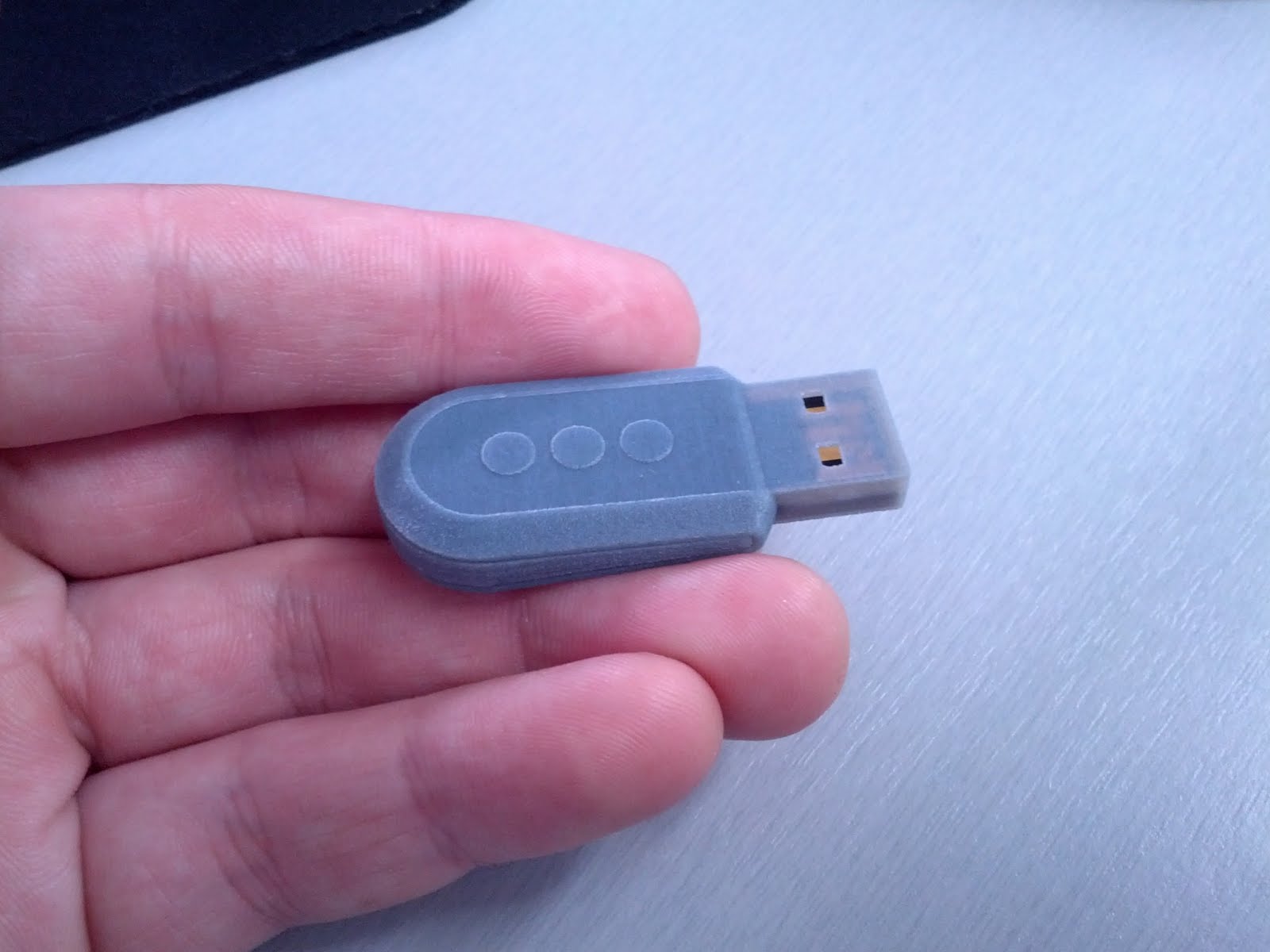
It may seem straightforward, but the change in how we perceive a design once it’s off a computer screen and in your hands is often surprising. In this case I had already used the end product. I added three raised circles to my design which were meant to enhance the appearance, but surprisingly helped orient the key properly in my hand.
USB Fit
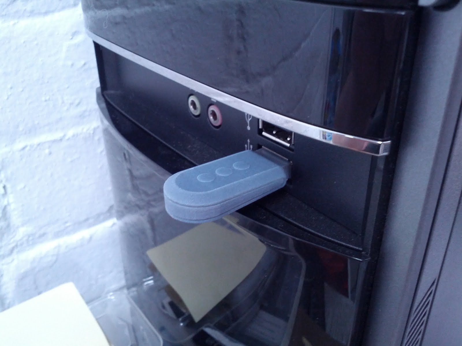
The interfacing test is one of my favourite, because it is very embarrassing to get wrong in production. In this case, I would have: I misread the USB spec and made the plug dimensions the same as the receptacle. When I went to plug my rapid prototype into the nearest office computer it didn’t fit! Although it’s good to catch as much as possible before making a rapid prototype, this is a perfect example of how rapid prototyping can save you time and money.
Snap Fits, Internal Fit and Assembly
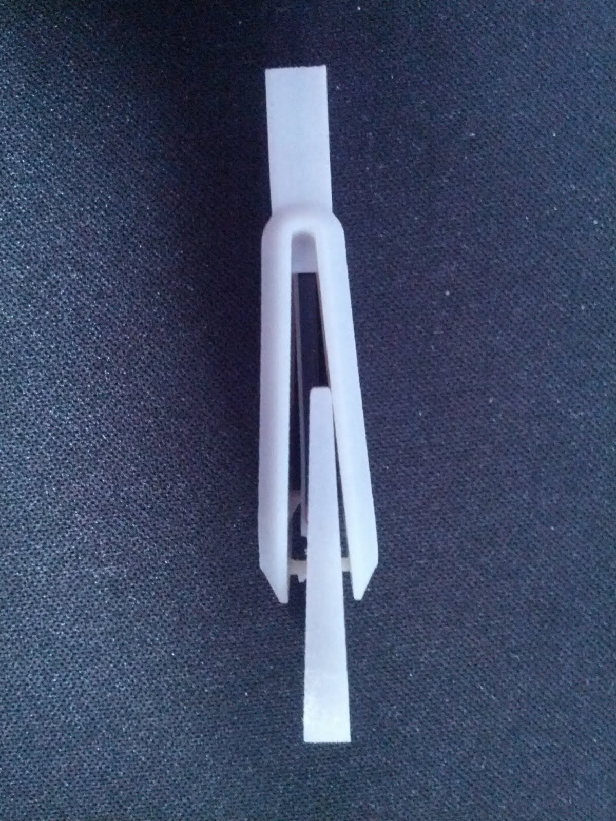
The existing memory module fit snugly into its carrier. The thin shelf flexed in a manner similar to the injection molded part to allow assembly.
Although you should run a clearance check before prototyping, it’s always good to see that your own parts fit with each other. The carrier and casing fit snugly with no accidental interferences or large gaps.
The snap fits worked to keep everything together, although they were not tough enough to survive repeated assembly. A future version would benefit from a slight rounding of the hook edge to make disassembly easier.
Assembly was smooth, although for a future revision I would widen the area on the carrier that is cleared to allow for smooth insertion past the snap fits.
The keying feature works as hoped, making it difficult to insert the carrier upside down.
Remaining Uncertainty
We’ve been able to eliminate a lot of uncertainty in our design. But it’s important to think about what is still uncertain, even after this rapid prototype.
- Manufacturability. Rapid prototyping can produce geometry that’s prohibitively expensive to produce with injection molding. You should evaluate draft angles, mold flow, undercuts, etc. separately.
- Strength. The jettable polymer materials we use are generally not as tough as plastics used in injection molding. You should evaluate this separately.
- Finish. Achieving a representative colour, surface texture or graphics will require extra work (we can help you with this too).
Conclusion
By “reverse prototyping” an existing injection molded part we’ve explored how 3DPhacktory’s rapid prototyping capabilities can eliminate common sources of design uncertainty. We also saw a hint at how rapid prototypes can help communicate, inspire and motivate by moving CAD models off the screen and into people’s hands.
For ordering and material information please see our industrial design page.
About the Author
 Paul Walker’s background is designing electronic and mechanical products for the film industry. Recently he’s been using his skills to design 3D printed movie props at 3DPhacktory.